An educational Ball-Balancing Robot. This project introduces some of the core concepts of robotics: programming, inverse kinematics, computer vision, and PID control.
Discord: https://discord.com/invite/WJuUWsy6DJ
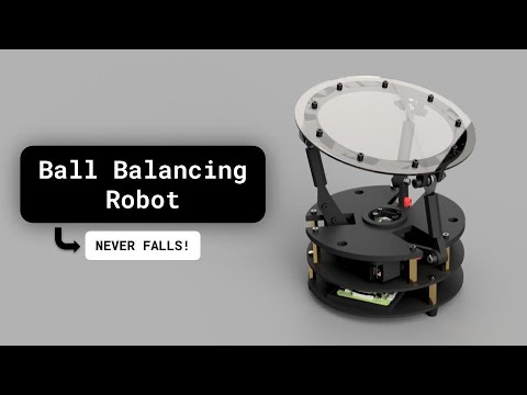


The 3D models and print profile for a Bambu A1 printer can be found here: https://makerworld.com/en/models/1197770-ball-balancing-robot#profileId-1210633
A Raspberry Pi–based ball balancing robot using real-time vision feedback and PID control.
Rev 9 represents a structural milestone:
- Clean
src/layout package structure - Separation of HMI and runtime
- Headless-safe runtime operation
- SSH auto-launch capability
- JSON-driven configuration
- Modular subsystem architecture
This section describes the full process from mechanical assembly to first runtime execution.
Refer to the Bill of Materials (BOM) for required hardware:
- Raspberry Pi
- Camera module
- PCA9685 I2C servo driver
- Servos
- Power supply
- Ball and platform hardware
- 3D print structural components.
- Assemble platform and servo linkages.
- Ensure:
- Platform pivots freely.
- No binding in linkages.
- Servo horns are mounted securely.
- Ball rolls smoothly across platform surface.
Mechanical slop or binding significantly affects control stability.
- Use Raspberry Pi Imager.
- Install Raspberry Pi OS (Bookworm recommended).
- Enable SSH.
- Configure WiFi if required.
- Set username and password.
Boot the Pi and confirm SSH access.
Wire components according to wiring instructions:
- Camera → CSI connector
- PCA9685 → I2C (SDA/SCL)
- Servo power isolated from Pi 5V rail (recommended)
- Common ground between servo supply and Pi
Enable I2C:
sudo raspi-config
# Interface Options → I2C → Enable
Reboot.
Confirm I2C device is detected:
i2cdetect -y 1You should see the PCA9685 address (typically 0x40).
Run installer:
bash scripts/install.shThis installs:
- Python dependencies
- System libraries
- OpenCV
- libcamera stack
Move Ballbot HMI.desktop to desktop
Launch the HMI:
hmiThe HMI runs over SSH using curses and provides jog controls and calibration tools.
Before applying offsets, establish a mechanical zero pose.
Procedure:
- Power the system.
- Arm the servos.
- Manually jog the platform until it is visually level.
- Trigger Zero Pose Capture from the HMI.
- Confirm the pose is recorded.
This step defines the neutral mechanical reference position for the platform. The zero pose is stored and used as the baseline for subsequent offset adjustments.
After zero pose capture:
- Fine-adjust X and Y offsets using jog controls.
- Observe platform level and ball behavior.
- Save calibration values.
- Disarm and re-arm to confirm repeatability.
Calibration values are written to:
config/calibration.json
After calibration:
- Platform should return to level at neutral command.
- No servo drift at idle.
- No bias in ball roll direction.
- Servo sounds should be symmetrical (no constant correction hum).
Accurate zero pose capture is critical for stable PID performance.
Start runtime from the HMI or directly:
bash scripts/run_runtime.shRuntime performs:
- Frame capture (~60 Hz)
- Vision processing (~50 Hz)
- PID control
- Servo actuation
If running over SSH (headless):
- Video preview is disabled automatically.
- Control loop remains fully functional.
Press q to exit runtime safely.
On shutdown:
- Servos disarm.
- Camera terminates cleanly.
Before declaring success:
- Ball remains near center without oscillation.
- No mechanical binding.
- Servos respond smoothly.
- No runaway tilt on startup.
- PID gains stable at low disturbance.