
Specification and characterization note based on the Booster wiki and selected issue history. Intended as a living technical reference for the project.
This document combines:
- product-level information from the public Booster wiki,
- measurement and behavior data from selected public issues.
It distinguishes between two variants:
- Booster — optimized for high efficiency,
- Booster-HL — optimized for high linearity.
Each measurement is linked directly to the source issue or issue comment where it was reported.
Booster is an eight-channel RF power amplifier providing several watts of RF between 40 MHz and 500 MHz in a 2U high 19-inch chassis.
According to the wiki, Booster is optimized for:
- low cost,
- low power consumption,
- good RF performance,
- full interlocking and logging via an Ethernet-based remote interface.
Source:
- Wiki home: https://github.com/sinara-hw/Booster/wiki
The wiki states that Booster is offered in two variants:
- optimized for high efficiency
- optimized for high linearity
- wiki statement: it offers the second harmonic at -40 dBc level
Source:
- Wiki home: https://github.com/sinara-hw/Booster/wiki
From the wiki:
- Ethernet interface for monitoring and configuration
- User-configurable interlocks protecting both Booster and connected loads
- Per-channel remote monitoring of:
- input power
- output forward power
- output reverse power
- temperature
- current
- voltage
- Remote shutdown of individual channels via Ethernet
- Open source hardware and firmware
- Modular design with individually field-replaceable channels, e.g. for changing frequency band
Source:
- Wiki home: https://github.com/sinara-hw/Booster/wiki
The wiki describes the following interlocks:
- implemented in hardware
- response time: a few microseconds
- user-adjustable threshold up to 39 dBm
- primarily intended to protect sensitive loads such as AOMs from excessive RF power
- fixed threshold: 30 dBm
- primarily intended to protect Booster itself from damage
- monitors internal 30 V and 6 V supplies
- includes hardware fold-back protection on the 30 V PA supply
- software protection disables a channel when temperature reaches 60 C
- thermal switch cuts power to the entire chassis at 80 C
- when any interlock trips, input RF is disconnected using an internal RF switch
- in an error condition, the amplifier power stage is also shut down
- interlocks can be cleared by:
- front-panel INTERLOCK CLEAR button,
- remote programming interface,
- power cycling
- error conditions require power cycling
Source:
- Wiki home: https://github.com/sinara-hw/Booster/wiki
From the wiki:
- input, output forward, and output reverse powers can be queried remotely
- channel temperature and fan speed can be queried remotely
- reported power values clip to the lowest accurately measurable value at very low power
- the onboard power readings are useful operational diagnostics, but should not be treated as test-and-measurement-grade RF instrumentation
- high VSWR can lead to dB-level errors in forward power readings
INTERLOCK CLEARSTANDBY
- by default, all channels are disabled at power-up
- MAC address can be obtained via the
macconfigcommand in the VCP interface - minimum fan level can be configured via
fanlevel - wiki guidance suggests checking typical idle current draws:
- 29 V should be approximately 50 mA with no RF
- 6 V should be approximately 250 mA
Source:
- Wiki home: https://github.com/sinara-hw/Booster/wiki
The RF input is protected using two TVS diodes SZNUP1301ML3T1G.
Key notes for the input stage:
- each TVS diode will continuously conduct approximately 215 mA
- after exceeding an input power of approximately 11 mW, the input behavior becomes reflective rather than absorptive
- in that regime the input can tolerate much more than 25 dBm
- under normal operation, the input is typically driven at 0 dBm
This is a design and usage note. Final guaranteed limits should be cross-checked against the schematic and dedicated input-protection calculations.
This section summarizes selected issues that are useful as source material for characterization.
Issue source:
Image:

Use:
- representative spectrum plot for Booster-HL
Status:
- typical characterization plot
Issue source:
Image:

Use:
- representative spectrum plot for Booster-HL
Status:
- typical characterization plot
Issue source:
Image:

Use:
- representative spectrum plot for Booster-HL
Status:
- typical characterization plot
Issue source:
Image:

Use:
- representative small-signal gain plot for Booster-HL
Status:
- typical characterization plot
Issue source:
Image:

Use:
- representative input return-loss plot for Booster-HL
Status:
- typical characterization plot
Issue source:
Image:

Notes pulled from the issue:
- small-signal S21 measurement with
Pin = -20 dBm - gain flatness looked good on most channels
- one channel showed poorer matching
- gain was reported as too high for that prototype
- the issue explicitly states this prototype result should not be considered acceptable as a production result without retuning
- issue #335 later adds useful context from Thomas Harty that a practical target of around 30 dB gain, or perhaps 35 dB absolute maximum, would likely be sufficient in real use, especially with Urukul-driven systems
Use:
- prototype characterization only
Status:
- not a final production specification
Issue source:
Image:
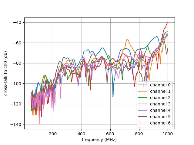
Notes from the linked source comment and associated public search snippets:
- no strong channel-to-channel dependence of crosstalk was reported
- below about 200 MHz, the author notes difficulty measuring it because crosstalk is reported as < 100 dB on most channels
- the linked plot is the primary source for crosstalk / channel-isolation characterization in this document
Use:
- typical characterization reference for channel-to-channel isolation / crosstalk
- strong candidate for a dedicated
Crosstalk / Channel Isolationsubsection in the final repo document
Status:
- characterization data from issue history/comment
Issue source:
Notes from the public issue history:
- Issue #95 exists specifically as the phase-noise tracking / documentation issue
- in #381, Thomas Harty explicitly states that the phase noise from Booster is incredibly low
- the same issue also notes that Booster has been used for high-fidelity quantum gates, which is a strong practical endorsement of RF quality
Interpretation:
- these are strong public qualitative statements about practical RF quality
- however, the currently extracted public content still does not include a directly embedded phase-noise plot in this document
Use:
- qualitative support for a
Low phase noise / demonstrated in precision AMO experimentsstatement - placeholder section awaiting direct phase-noise plots from Harty's measurements if they are recovered from issue comments or other public attachments
Status:
- qualitative public evidence with the correct dedicated source issue linked, but still missing a hard plot-based phase-noise figure in this document
Issue source:
Image:

Notes from the issue history:
- in #258, Thomas Harty reports observing a small bistability on Booster's power detectors
- he reports operation at constant power, frequency, and phase from Urukul while logging Booster diagnostics through the VCP interface
- the observed change is approximately 0.3 dB, with a simultaneous change in noise
- the only correlation he reports spotting in diagnostics is that the 5 V MP voltage changes slightly at the same time
- in #181, Harty also states that after testing, Booster v1.3 seemed to work really excellently apart from outstanding software issues
Interpretation:
- #258 is best treated as a characterization/debug note for diagnostic stability or detector bistability, not as evidence of output-spectrum instability by itself
- it remains a useful source because it documents a concrete stability-related observation together with a diagnostic screenshot
Use:
- characterization note for diagnostic stability / bistability behavior
- candidate material for a
Diagnostics stabilityorKnown behaviorssubsection rather than a headline datasheet claim
Status:
- useful stability-related figure and observation; not a standalone general RF-output stability limit without additional external-power-meter correlation
Issue source:
Images:


Notes pulled from the issue:
- reported for a 150 MHz signal
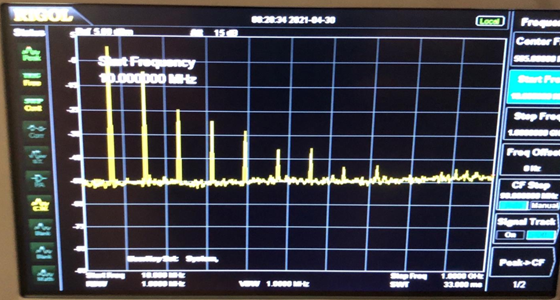
- issue states that Booster showed high harmonic content in that test
- the issue explicitly states: "The Booster was optimized for efficiency, not for linearity."
Use:
- important caveat for the standard variant
- useful for explaining the Standard vs HL split
Status:
- reported caveat
Issue source:
Use:
- public discussion that helps justify wording such as:
- standard Booster prioritizes efficiency and lower dissipation,
- Booster-HL exists for better linearity
Status:
- positioning source rather than a direct measurement plot
Issue source:
Image:

Notes pulled from the issue:
- approximately 0.6 dB AM distortion
- reported at 33 dBm
- observed during full AM keying
- reported on two time scales
- reported as less severe at lower powers
Use:
- dynamic behavior caveat
- candidate for application note or characterization section
Status:
- reported caveat
Issue source:
Images:
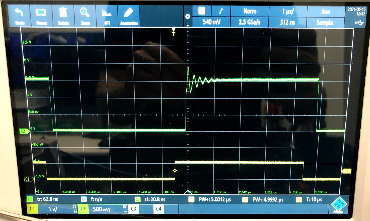
AOM optical pulse:
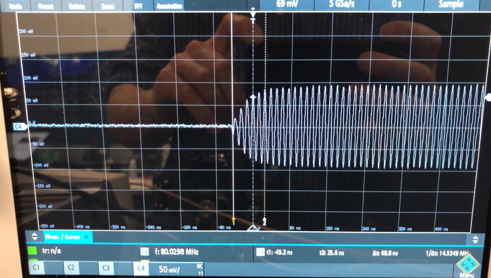
RF pulse out of Urukul:
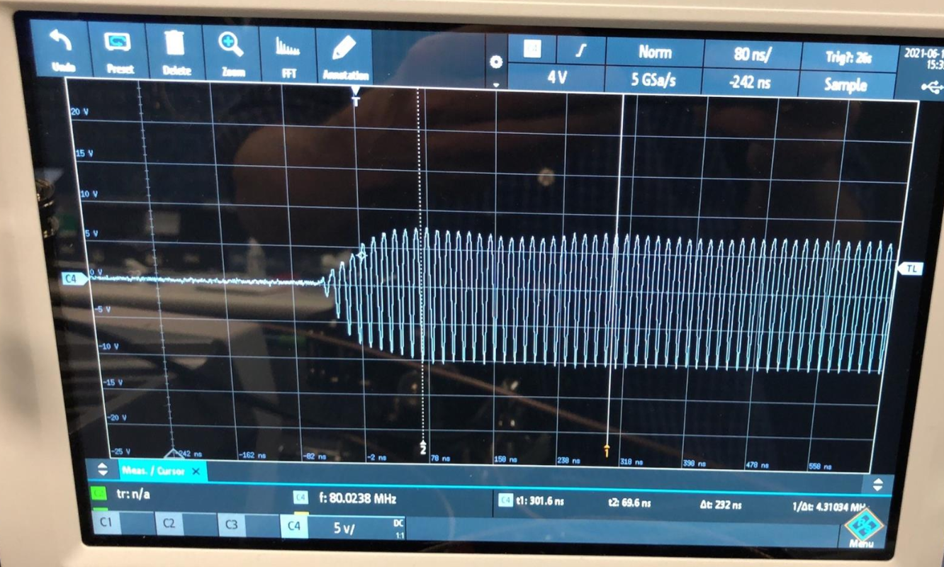
RF pulse out of Booster:
Spectrum with visible second harmonic:
Notes pulled from the issue:
- reported in an
Urukul -> Booster -> AOMchain at 80 MHz - ringing observed in the optical pulse
- ringing and asymmetry observed at Booster RF output
- issue text mentions a second harmonic around -9 dBc in that setup
- swapping to a Mini-Circuits amplifier reportedly removed the observed ringing in that user setup
Use:
- application-level transient caveat
- useful as a characterization note rather than a headline spec
Status:
- reported caveat
Based on the current public wiki and the selected public issues, this document can state:
- Booster is an 8-channel RF power amplifier platform covering 40–500 MHz
- Booster is available in:
- a high-efficiency version,
- a high-linearity version
- Booster includes Ethernet monitoring/configuration, interlocks, and per-channel telemetry
- the wiki states that Booster-HL offers second harmonic at about -40 dBc
- public issue data for Booster-HL cover:
- spectra at 150 MHz
- output levels of 30 dBm, 33 dBm, and 34 dBm
- S21 and S11 from 40 MHz to 800 MHz
- public issue data also document important standard-version caveats and characterization related to:
- gain versus frequency for prototype hardware
- crosstalk / channel-to-channel isolation
- harmonic content
- AM keying distortion
- ringing in some AOM use cases
- public issue historys also provide qualitative support for very low phase noise and strong practical stability, but this document still lacks the underlying hard plots that would be needed for a formal datasheet claim
- the RF input protection note in this document states the use of two SZNUP1301ML3T1G TVS diodes and a typical operating level of 0 dBm; final guaranteed limits should still be cross-checked against the primary design sources
Before promoting this into a formal datasheet, the following items should be validated:
- guaranteed output power by frequency band
- flatness / gain tolerances across channels
- harmonic content limits for production hardware
- startup / pulsed / AM transient behavior
- measurement conditions behind the wiki claim for Booster-HL second harmonic
- direct phase-noise plots and long-term stability plots from Harty testing
- direct crosstalk figures from the linked issue comment, if they are to be embedded locally rather than linked
- environmental limits, cooling assumptions, and warm-up conditions
- connectorization, power input, mechanical dimensions, and exact revision scope